|
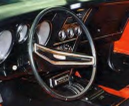
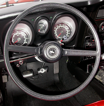
Two and three spoke wheels for the 71 Cougar are
shown above. |
| Steering |
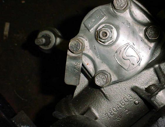
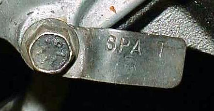
Power Steering Gearbox
The 71 429 Mustang (and other V8 models with
competition suspension) came with Variable Ratio Power Steering, which
provided a rapidly reducing ratio as the wheel is turned beyond center.
This gave the driver the benefits of quick ratio steering without the
steering being super-sensitive. The 71 -72 variable ratio P/S gear boxes
were tagged "SPA-T" (see below) and "SPA-V". The SPA-T was
definitely used on the '71. It is not known at this time if the SPA-V was
also used in '71 or was for '72 only.
71 -72 Mustangs without the Competition Suspension used
a Constant Ratio P/S gearbox listed as SPA-S and SPA-U.
|
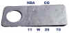
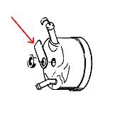
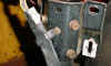
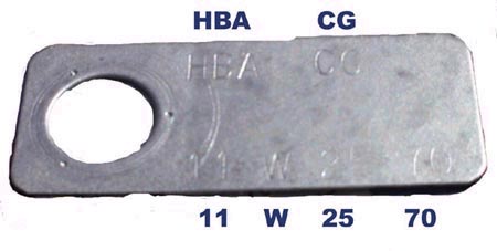
Power Steering Pump Build Tag
Two different power steering pumps were used on the 71
Mustang. The HBA-CG was used with the variable ratio gear box and the HBA-CF
was used with a constant ratio gear box. The ID tag is located on the back
of the pump as shown in the drawing below.
|
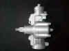
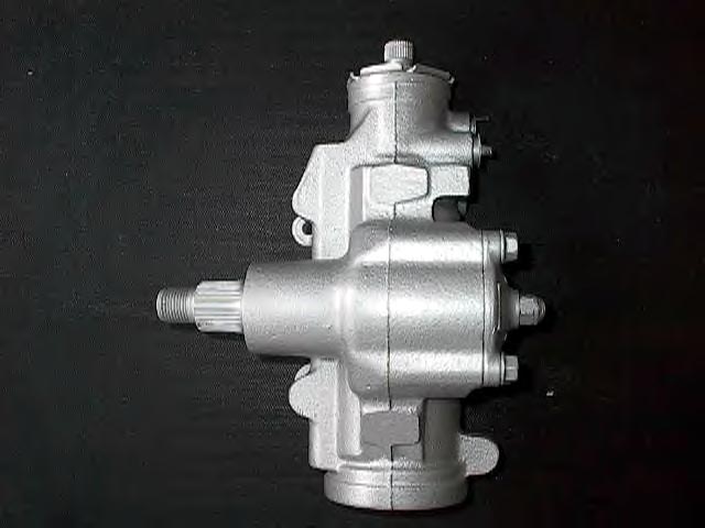
Power Steering Gearbox
|
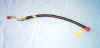
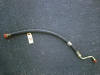
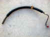
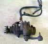
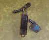
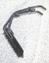
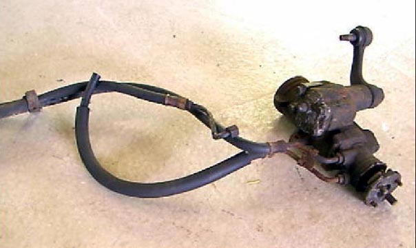
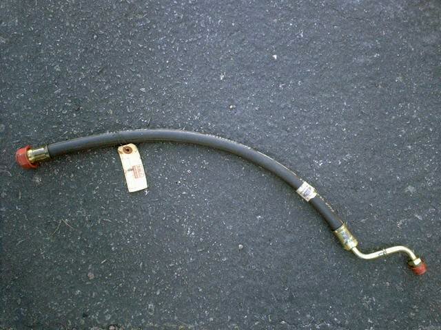
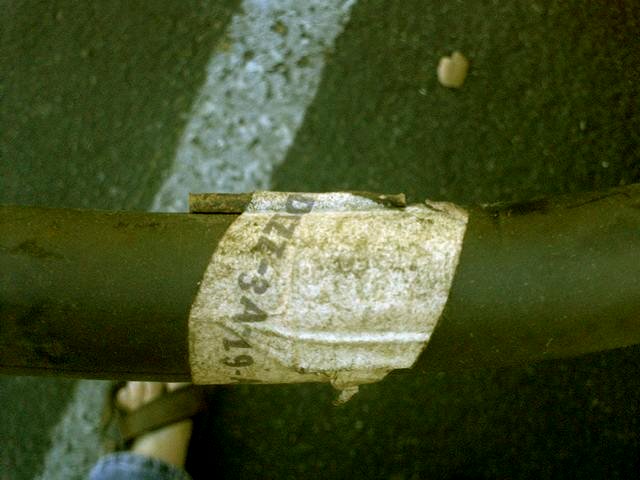
Power Steering Hoses
The 429 pressure (inlet) hose D1ZZ-3A719-A is shown in
the top row above. The
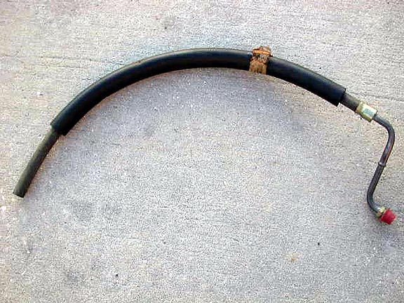
return hose is shown in the second row above with the insulating foam protective sleeve.
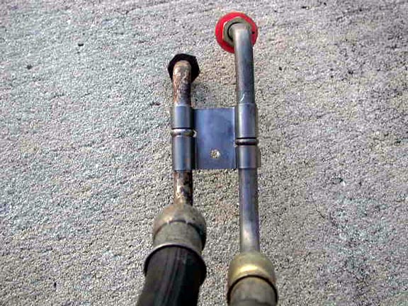
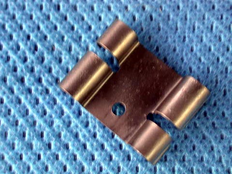
The clip shown below maintains the hoses in the correct design position
and prevents rotation into other components.

|
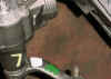
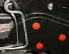
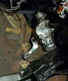
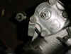
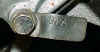
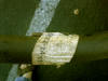
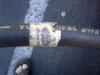
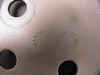
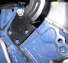
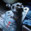
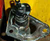
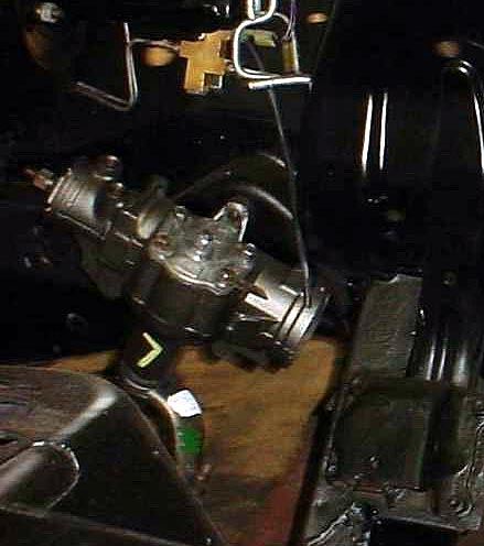
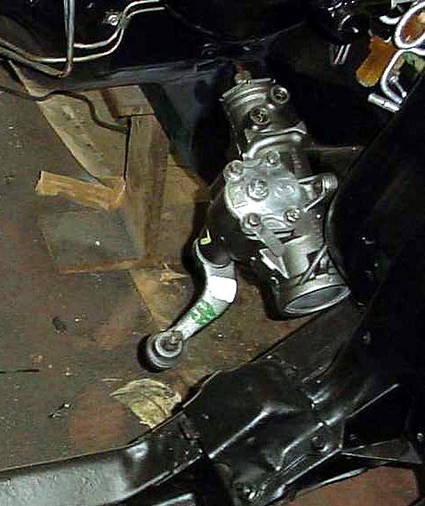
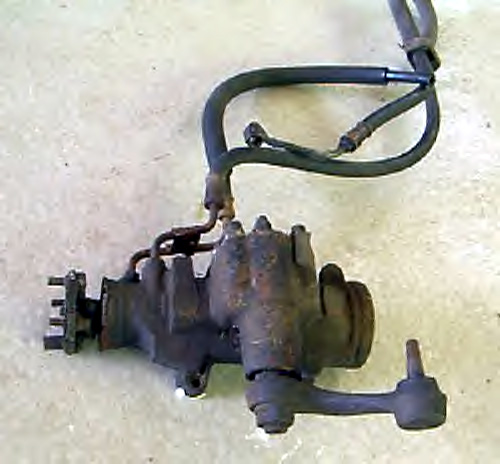
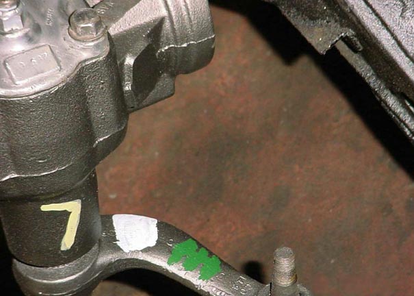
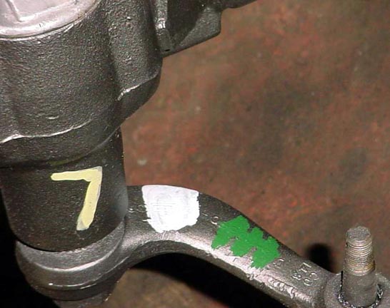
Power Steering Gear Box Paint Marks
The two photos above show paint marks on the P/S gear
box and associated parts. A yellow "7" on the gear box itself, a
white dab and green "M" (or "W") on the pitman arm,
and the heads of the 3 bolts which attach the gear box to the frame are
red oxide dyed finish as a corrosion protectant. These paint marks are all careful reproductions of the
originals found on this particular box, which is from a 71 Boss 351. Since
the Boss 351 and 429 CJ/SCJ share the same variable ratio steering box, it
is assumed that the 429 would have these same markings.
|
|
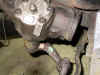
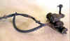
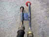
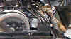
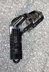
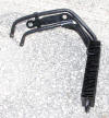
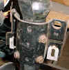
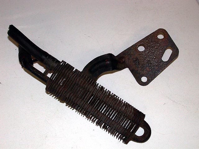
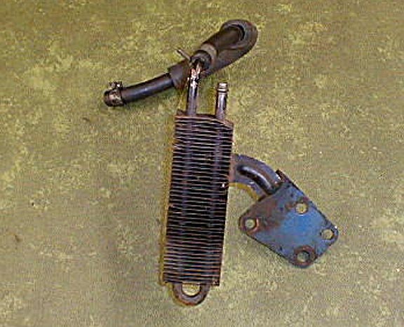
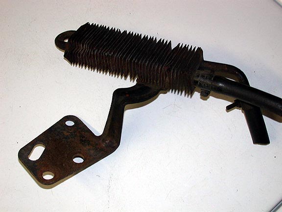
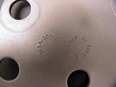
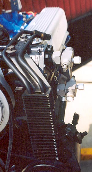
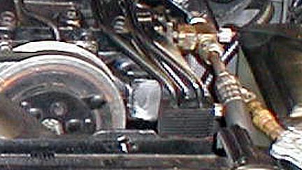
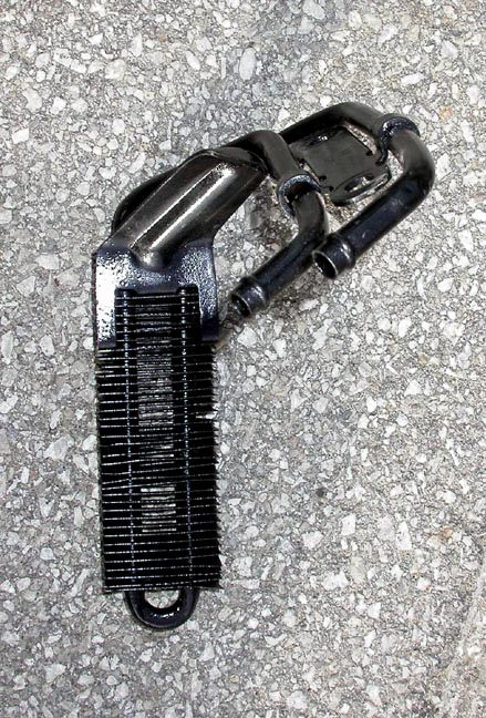
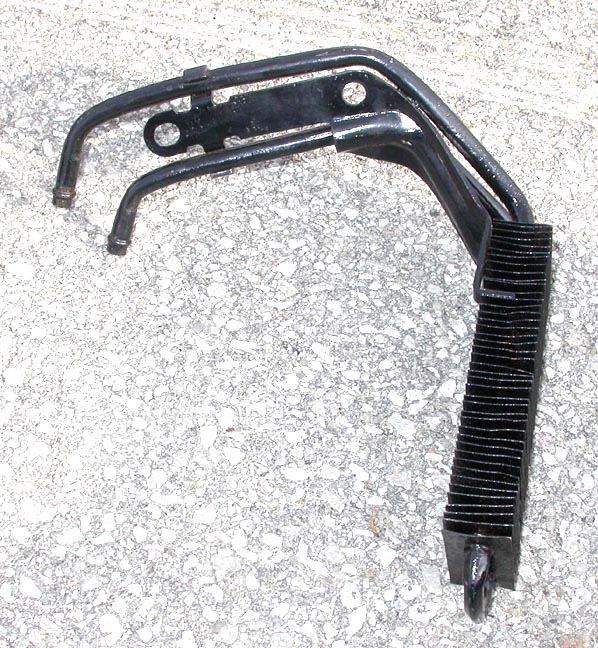
Power Steering Cooler (Non A/C)
Shown is the unique CJ/SCJ cooler
(part#D1AA-30746-BA) which mounted to the left cylinder head, and was used
on some non-A/C cars. The part number is shown in the closeup photo
below left and the location the cooler bolts to the head at right.
|
|
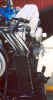
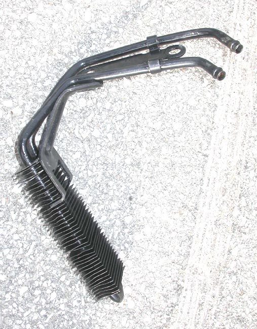
Power Steering Cooler (A/C)
Some CJ A/C cars used the standard Ford
cooler (above - part# D1AA-3D346-AA or AB) that was different from the one
shown at left. It was mounted on the top of the A/C compressor as
shown above.
|
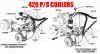
PS Cooler Diagrams
This diagram shows how the Power Steering coolers are
mounted for both the A/C and non-A/C versions.
|
|
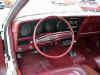
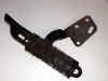
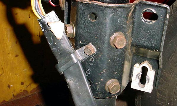
Steering Columns
At left is the 71 steering column and the 72 at right.
Note the date code on the mounting plate on the 71 version and the
differences in wiring locations between the 71 and 72 versions.
|
|
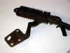
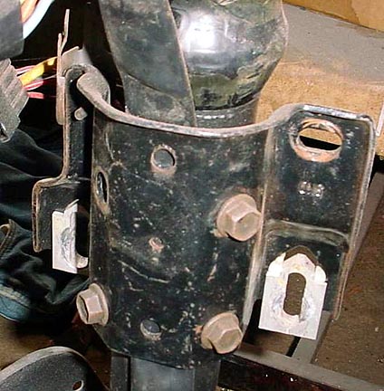
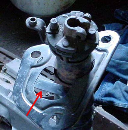
Steering Mounting Plates
A Steering Mounting plate for and Auto Trans
application is shown at left and one for a manual trans is shown at right.
Note the strip of metal in the opening of the auto trans version at red
arrow while this strip is absent on the manual trans version. If you have
a mounting plate for an auto trans car and want to use it for a 4 speed
car, all you need to do is cut the strip out. That is the opening
that the clutch rod passes through.
|


