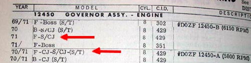
|
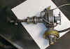
D1AF-12127-NA single point distributor used on the C6
automatic 429 CJ/SCJ
|
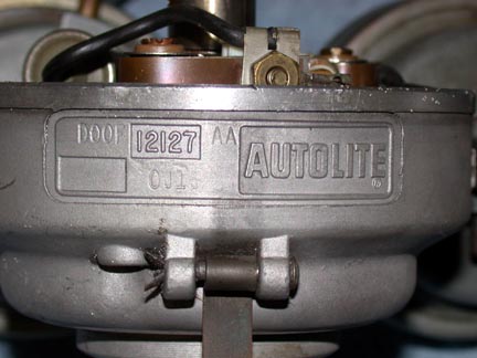
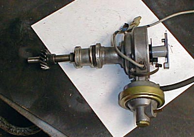
D0OF-12127-AA dual point distributor used on the 4
speed CJ/SCJ
|
Autolite Cap |
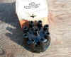
Top view of D1AF-NA single point.
|
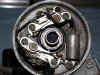
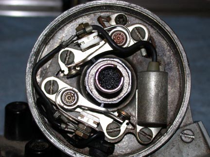
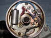
Top view of D0OF dual point.
|
D0OF-AA Dual Point for 4 speeds.
|
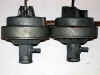
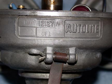
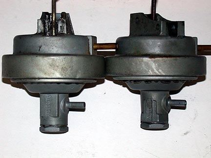
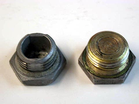
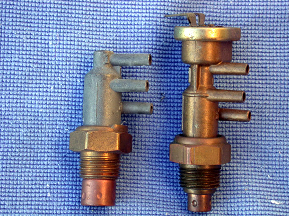
Vacuum Advance
The photo above shows the Autolite vacuum advance units
side-by-side. The wider band advance on the left ( 11/16") is a 4 speed unit. The
thinner band advance on the right (9/16") is a C6 unit. Note that in
'71, the vacuum advances changed to
a "cast-in" front nipple instead of pressed or screwed in
steel front nipple like previous years. Both units have this
"cast-in" front nipple that was used from July '70 through '71.
A Word About Band Color
Although not evident in
our side-by-side photo above, the wide band (11/16") for Manual
Transmissions is the gold CAD plated. The narrow 9/16" ban for Automatic
Transmissions is silver CAD plated.
|
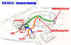
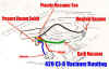
Vacuum Hose Routing Diagrams
|
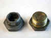
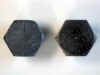
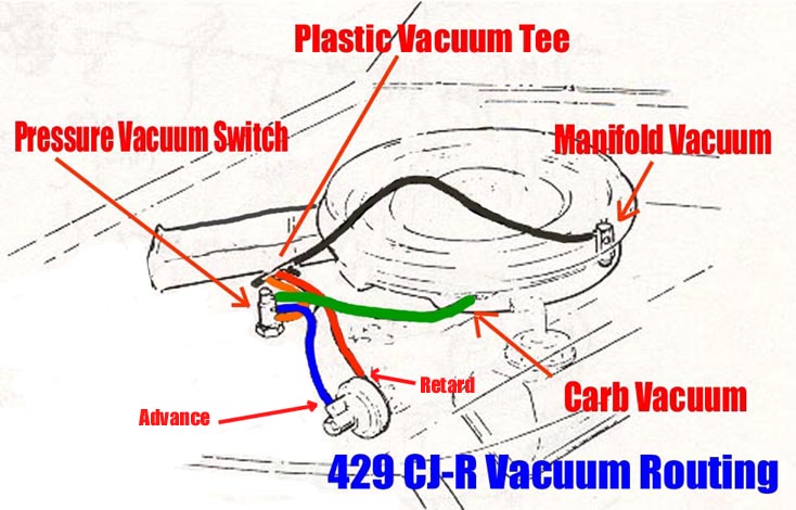
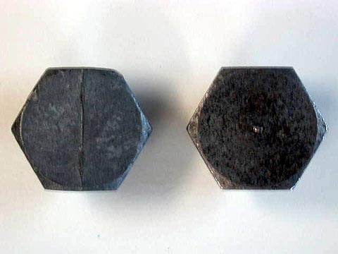
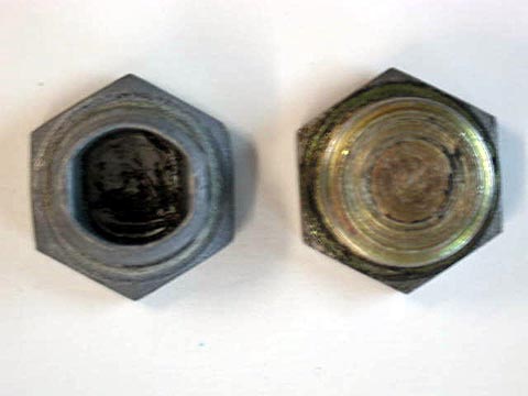
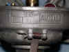
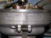
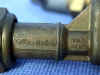
Vaccum Advance End Plugs
These photos show the difference in the end plug for
the front chamber of the dual advance unit on the distributor. The 67 - 70
vacuum advances used a steel plug (right, in above photos) whereas the 71
switched to an Aluminum plug (left in photos above).
|


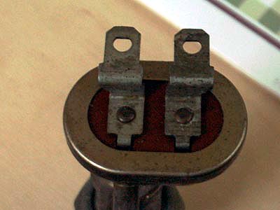
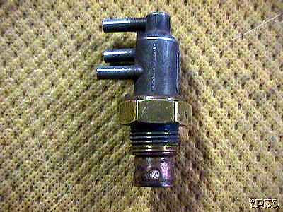
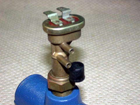
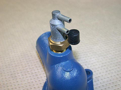
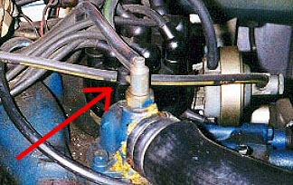
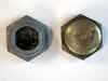
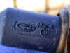
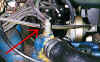
Distributor Control Switches
The picture at left is a side by side comparison of a
PVS (Ported Vacuum Switch) and an EPVS (Electric Ported Vacuum
Switch). These switches mount on the thermostat housing and provide vacuum
control to the distributor based on coolant temperature. Some 429 CJ and SCJ engines
have the EPVS (close-up center) while most others have a 2 or 3 port "vacuum only"
PVS control
valve (3 port version shown at right). Research is currently ongoing to understand the purpose of the
electric feature on this valve and why it was used on only some
429 CJ/SCJ engines. This information will be updated when we reach some
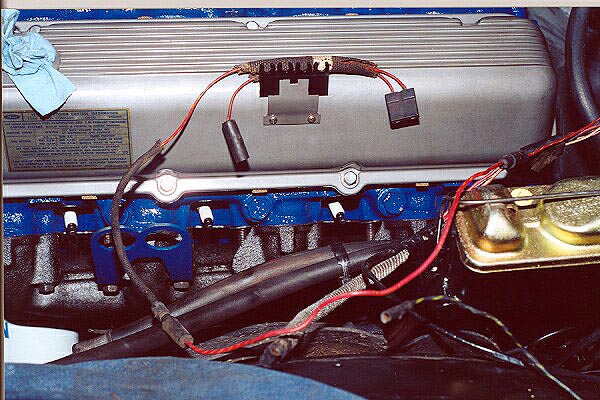
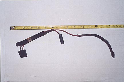
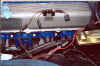
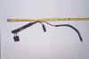
conclusions. Two views of the special wiring harness used for the EPVS are
shown below.
|
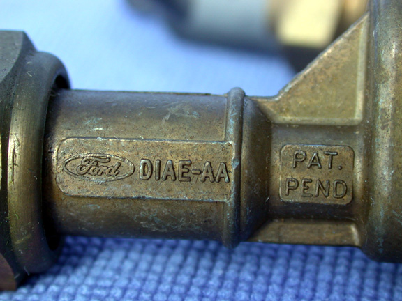
EPVS
(Electric Ported Vacuum Switch)
D1AE-AA |
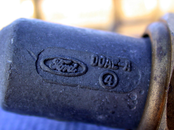
PVS
(Ported Vacuum Switch)
D0AE-A |

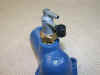
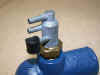
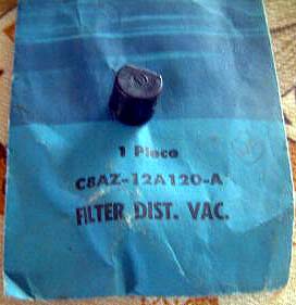
EPVS/PVS Air Filter
This small air filter was placed on the lower nipple of
the vacuum switch to prevent debris from entering the air intake port of
the switch. The photo at far right shows one of these filters installed on
an all original 429 SCJ Mustang.
|
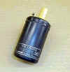
Coil
This is an original 12 volt Autolite Yellow Top Coil as
was used originally on the 71 Mustang/Cougar (and most other Ford products
of that timeframe). It carries part number FAC-12029-A. If you are using
an aftermarket high performance coil, you can simulate the appearance of
the original by using yellow Testors model paint on the coil cap. A decal
with the Autolite logo and part number is available from most Mustang
parts houses.
|