|
|
|
|
|
|
|
| 429 SCJ Thermactor System |
| System Overview |
|
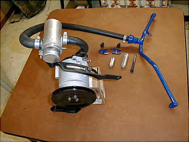
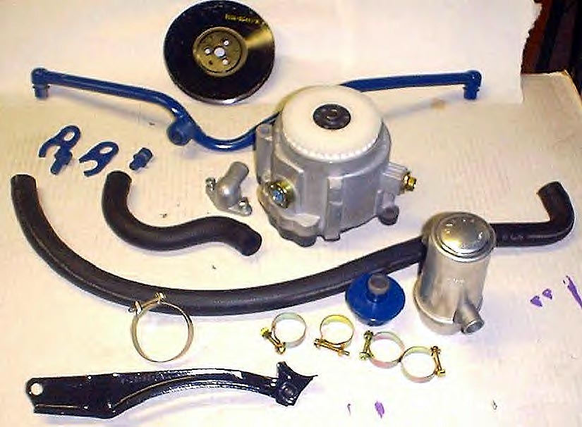
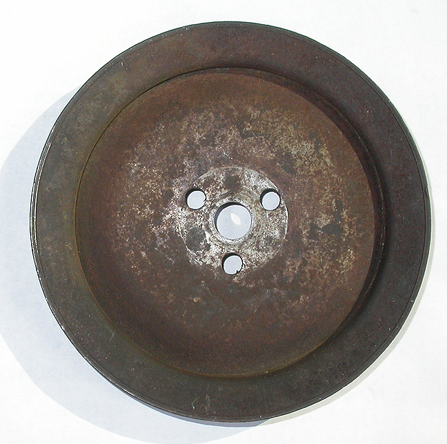
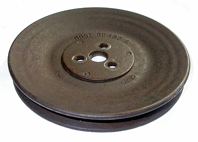
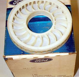
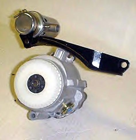
Complete Thermactor System The complete Mustang/Cougar/Torino SCJ smog system was taken from the 70 -71 460 Lincoln line, except for the pump pulley, which is a unique 70 T-Bird part. The pulley may have been left over parts stock, since "smog" wasn't available for the 70-71 429 T-Bird. This would make the SCJ smog pulley quite rare today. An assembled 429 SCJ Mustang system is shown above and all of the individual components are below. Note the very rare D0SE pulley in the photo below right.
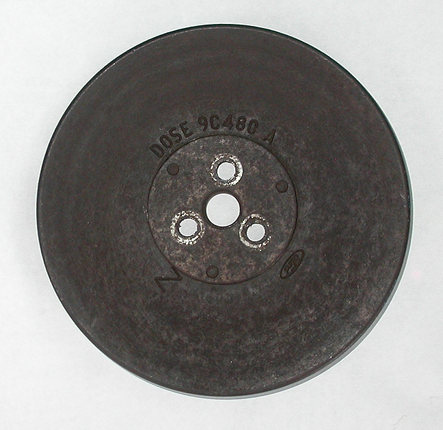
Smog Pump Pulley The D0OE pulley
was used on all California emissions 429/460 engines.
These engines were found in Lincolns, T-Birds, Galaxies,
Marquis', etc. Oddly enough, the 429SCJ engines used an entirely
different pulley numbered D0SE. The difference is in the offset,
with the D0SE pulley having near zero offset and the D0OE pulley
having 3/4" or so. Yup, the engineering numbers seem backward,
but that's the scoop.
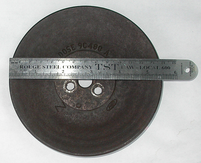
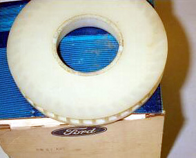
Photos Below are of the D0SE Pulley (Thanks to Jerry Ostalecki for providing)
|
|
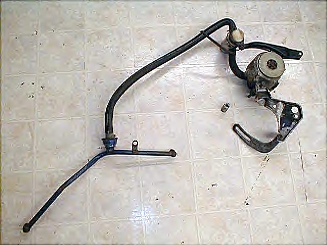
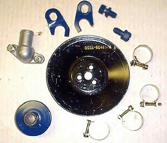
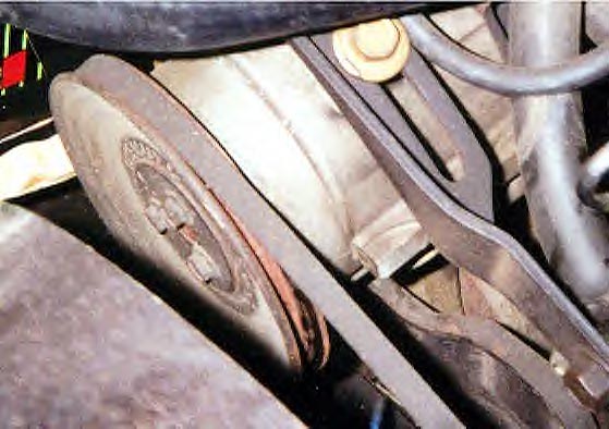
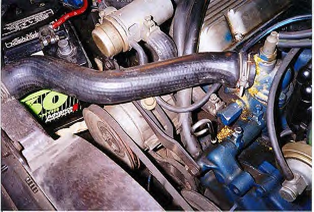
View of System Installed The photos above are of the Smog
system on Fred Coyner's low mileage all original 429 SCJ
Mustang. The smog pump pulley was stamped D0SE-9C480-A, and had
a 5 1/2" diameter with a 15/32" sheave.
|
| Details on Smog System Components |
|
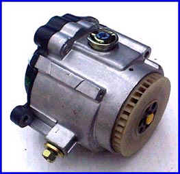
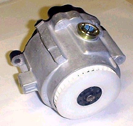
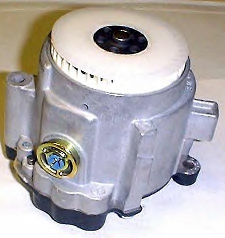
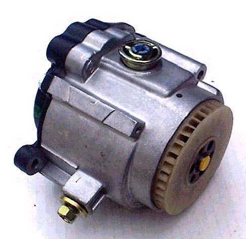
SMOG (Thermactor) Pump Here is the 68-71 Thermactor pump (C8AZ-9A486-C) used on the 429 SCJ Mustang. This pump featured a round pressure relief valve in it's side. The color of the valve was blue with a gold cad frame. The pump itself was bare aluminum, with an aluminum 90 degree hose nipple. The pump also had a semi-black cast iron rear housing with silver hardware. The pump used a white centrifugal filter fan in the front, and the pump's shaft end was painted yellow. If you're looking for a Smog pump, note that pumps from the mid 70's will work, but they didn't contain the pressure relief valve. The correct white pump fan is shown below.
|
|
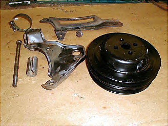
Attachment/Mounting Parts The photo above left shows the
smog belt adjustment bracket (long one) which was marked
D0VE-9B452- A. Just below this is the small triangular bracket
(marked D0VE 9C486 A) that held the by-pass/diverter valve to
the belt adjustment bracket. This triangular valve bracket,
along with the 2" round clamp was only used on cars built
before 3/1/71. The SCJ water pump pulley, which was the same as
the CJ w/ PS w/o A/C, was marked D0OE-8509-M. To the left
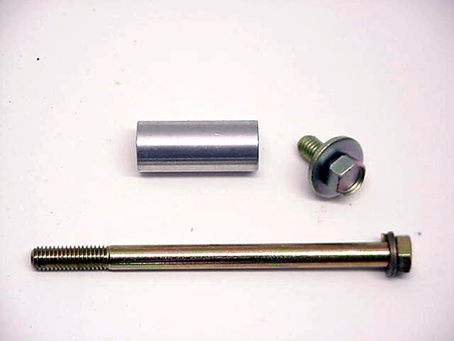
of the pulley is the alternator bracket. The pumps mounting bolt
was 6" long, and the pumps spacer was 1 13/16" in
length (photo at right). |
|
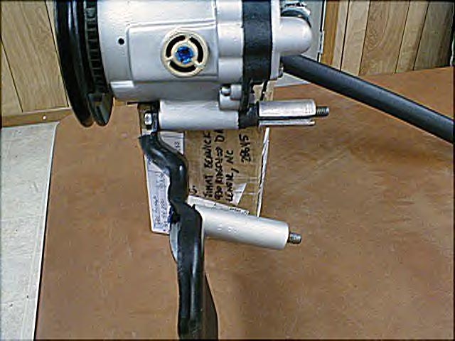
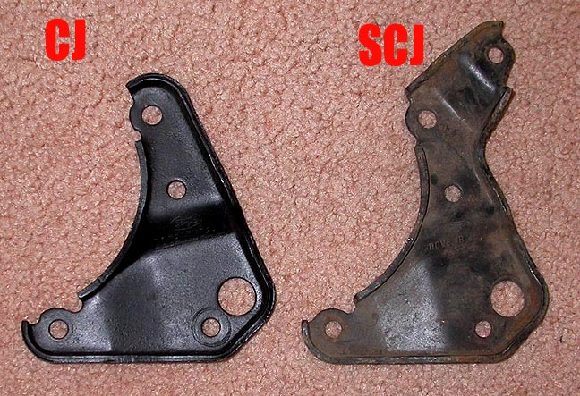
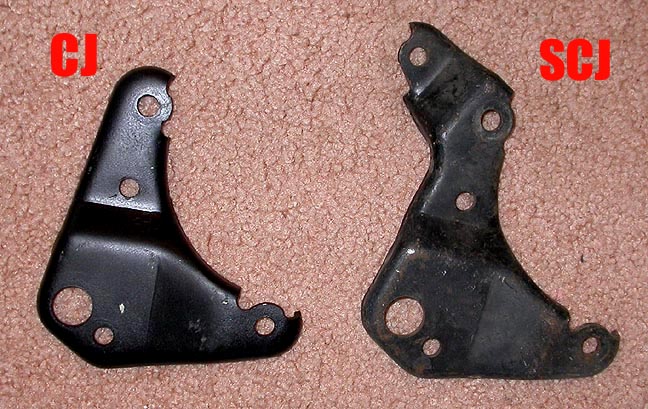
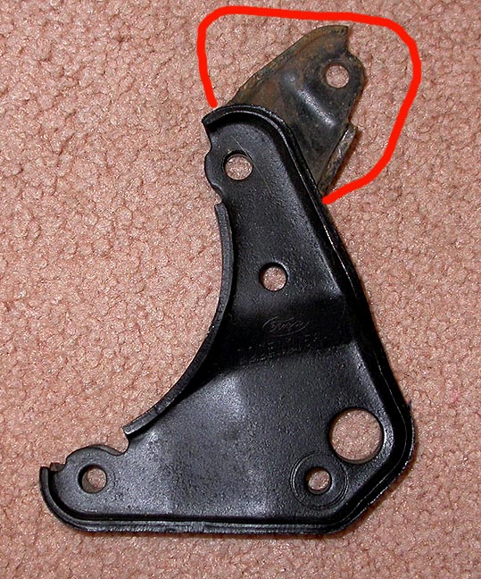
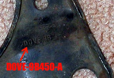
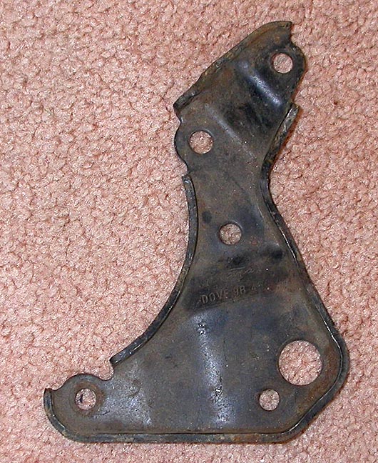
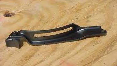
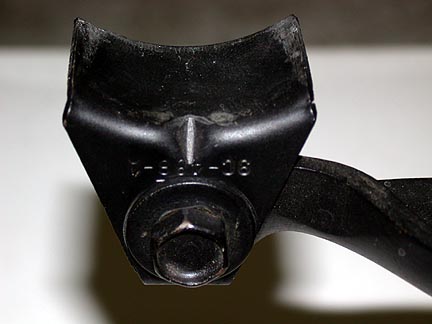
Smog Pump Mounting/Alternator Bracket The 429 SCJ uses a modified 429 CJ alternator bracket to mount the Smog Pump to the engine. As can be seen in the photos above, Ford added an additional mounting tab to the CJ bracket to serve as the lower mount for the Smog Pump. This mounting tab can be clearly seen in the photo at center right with the CJ bracket overlaid on top of the SCJ bracket. The SCJ bracket is part number D0VE-9B450-A as shown in the photo at top right and bracket alone is shown below;.
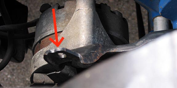
Below is a view of this bracket installed (without smog pump) showing the eyelet that provided the lower mounting point for the smog pump.
|
|
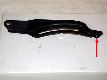
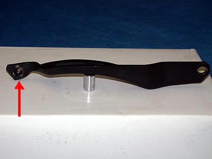
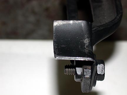
Smog Belt Adjustment Bracket The pictures above show two angles of the D0VE-9B452-A smog pump belt adjusting bracket. The red arrow shows the installation location of the D1VE-9C486-AA by-pass valve mounting bracket. Below is a view before and after installation of the D0VE-9B452-A smog pump belt adjusting bracket. |
|
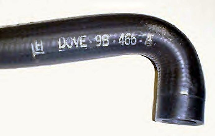
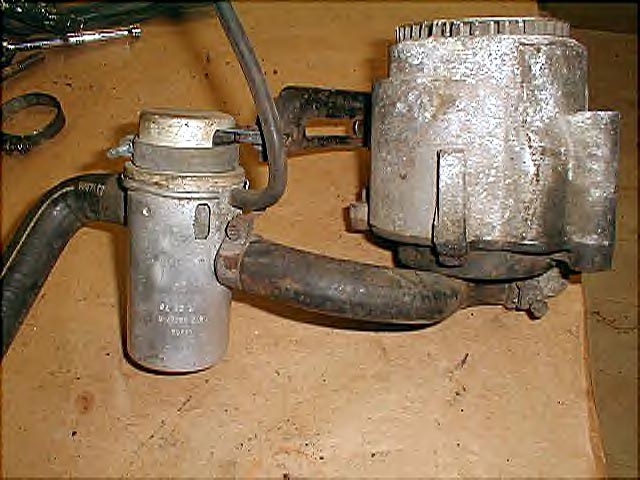
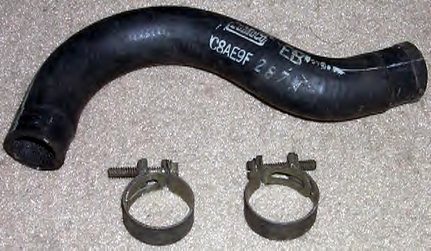
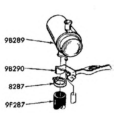
Bypass/Diverter Valve Here you can see the air by-pass/diverter valve with it's cover in place. The cover was stamped C8TE-9B289-B, and also was stamped with the valve's build date. Normally, the pumps output air flowed to the cylinder heads exhaust ports whenever the engine was running. What this did was inject fresh oxygen into the hot exhaust gas, and this caused any remaining unburned fuel to be re-ignited in the exhaust port and be reburned to lower the exhaust emission level. Now, during times of engine deceleration, the pump's air flow was diverted for 3 seconds from the cylinder heads, and sent to the 2 oval exit slots in the by-pass valve's cover. The cover also acted as a muffler for this by-passed air. The by-pass of the pump's air from the exhaust ports was done to prevent exhaust backfiring during engine deceleration when the engine's air/fuel mixture would go slightly too rich. You will sometimes see the by-pass valve called an "anti-backfire valve". The Pump to Diverter Valve Hose and correct attaching clamps are shown at loer right. This short "S" hose was 8 3/4" long, and was stamped C8AE-9F287-A.
|
| Bypass/Diverter
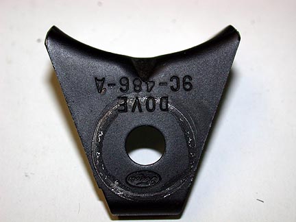
Valve Mounting Brackets There were two different mounting schemes for these Bypass/Diverter Valve. These are described below. |
|
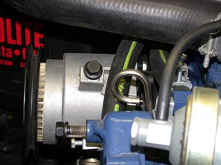
Bypass Valve Bracket used from 8/70 thru 2/71 The triangular bracket shown above left is the by-pass valve mounting bracket that was used on cars built from 8/70 thru 2/71. It's part number is D0VE-9C486-A. The D0VE-9C486-A by-pass valve mounting bracket mounted to the D0VE-9B452-A smog pump belt adjusting bracket (above center and right). As shown below, the by-pass valve is placed in the curved saddle formed by the D0VE-9C486-A mounting bracket and a clamp goes around the by-pass valve housing and tightens against the curved underside of the mounting bracket. An installed view is shown below right.
|
|
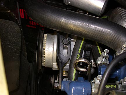
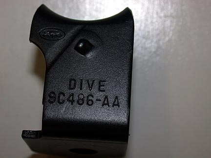
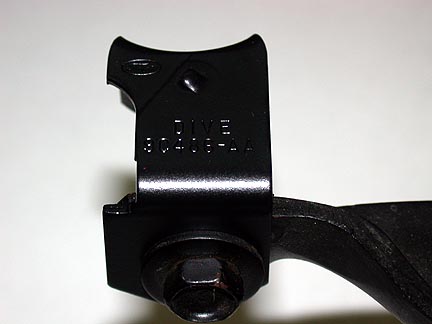
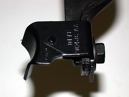
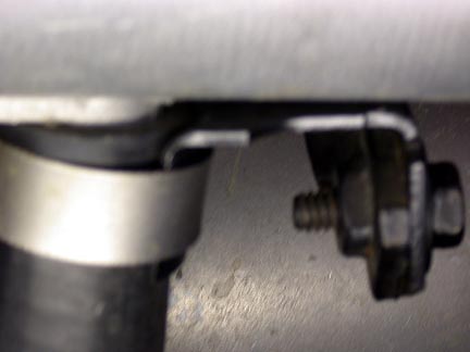
Bypass Valve Bracket Change on 3/1/71 The diagram above shows the by-pass valve mounting bracket that was used on cars built from 3/1/71 on. The bracket switched from the triangular D0VE-9C486-A to the D1VE-9C486-AA shown in the photos above on 3/1/71. The photos below show the D1VE-9C486-AA by-pass valve bracket mounted to the end of the D0VE-9B452-A the smog belt adjustment bracket..
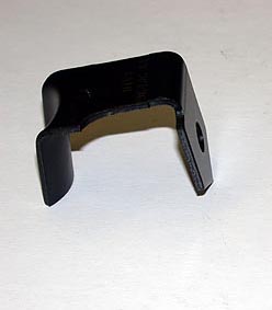
The photos below show how the curved surface of the D1VE-9C486-AA bracket clamps to the hose (Smog Pump to by-pass valve).
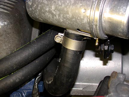
A final installation view of By-Pass Valve on the 3/1/71 level bracket is shown below. Note that the By-Pass Valve is clocked so the rear of the canister is pointing at 1:00 (instead of 12:00 on the pre 3/1/71 design). This clocking of the valve was necessary to gain clearance between the support bracket and the nipple on the bottom of the canister. This angle change is also shown in the MPC diagram at lower right.
|
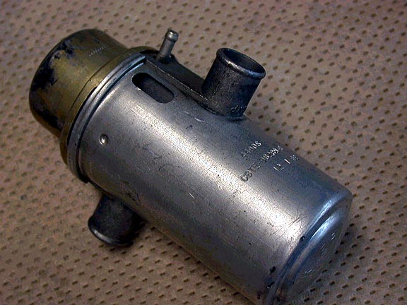
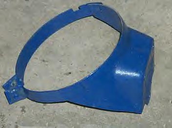
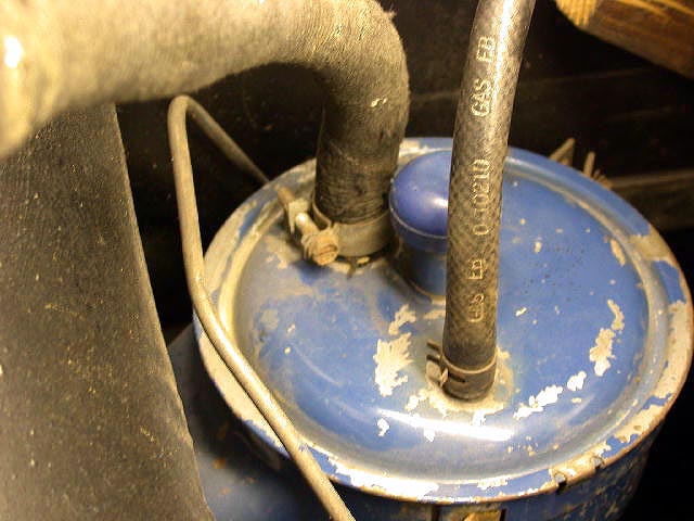
| Evaporative
Emissions Recovery - Charcoal Canister
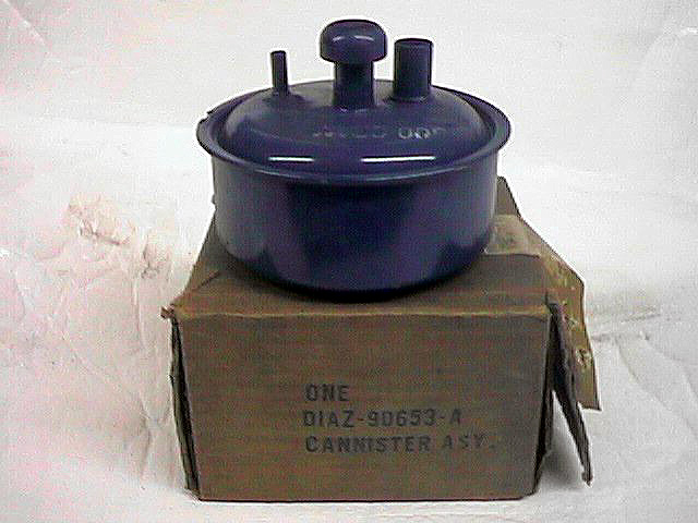
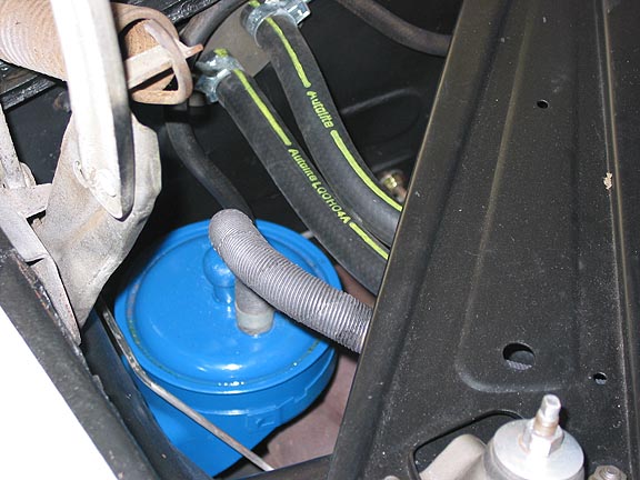
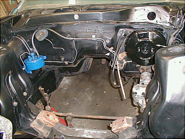
The charcoal canister was found on bothe the 429 CJ and SCJ applications. |
|
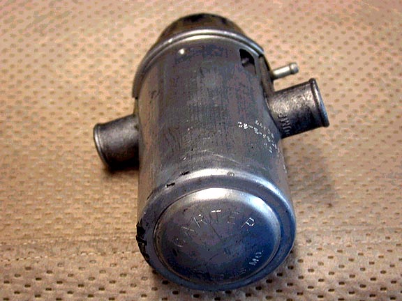
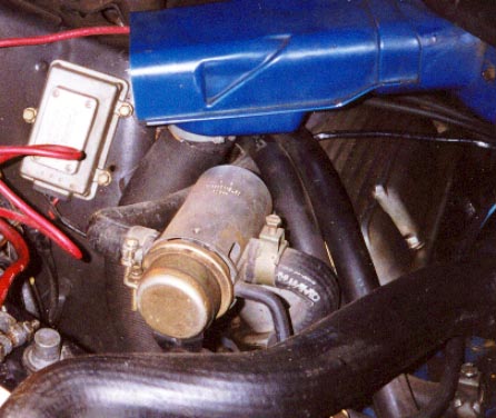
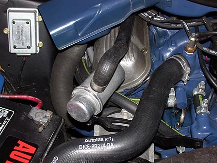
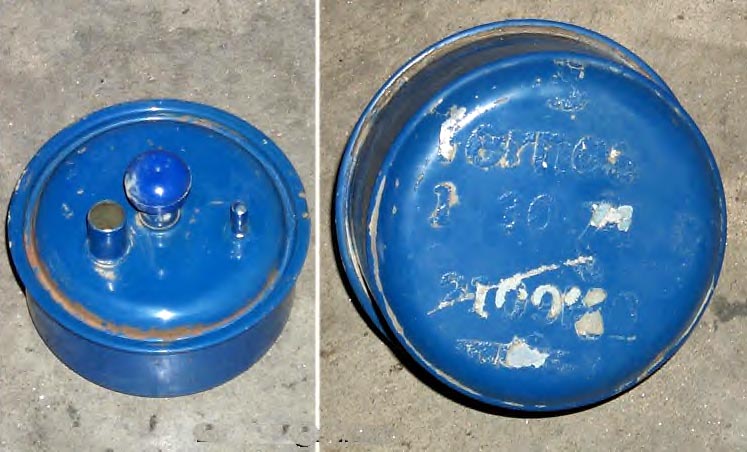
Charcoal Canister This is the charcoal canister. It was mounted in the engine compartment (rear of passenger side as shown above) to the inner fender apron with a bracket. The inlet side (small fitting) hooked up to a tube from the fuel tank. The outlet side (larger tube) ran to a fitting on the air cleaner (with a filter element). When the engine was running, it served as a system to aspirate and burn excess gasoline fumes to prevent the fumes from escaping to the atmosphere. Additional photos of the canister and it's attachment bracket are shown below as well as an original showing factory hoses and clamps.
|
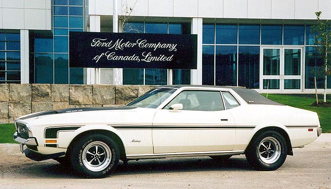
Greg Wong's 429 CJ Grande